This is the ‘Tin Can Radio’ by Victor Papanek and George Seeger. There appears to exist exactly three images of this thing online. It’s a radio reciever from 1962 intended for ’third world’ countries. From texts referencing it, it’s generally explained that the radio is not selective (it can not be tuned), that it is somehow powered by burning candle wax or cow dung in the tin can, it features a transitor (?), a 9 cent bill of materials and is possible to assemble by hand.
Okay, but how does it work? I don’t know the first thing about RF circuitry but in short: It’s a selector-less crystal radio utilizing a tunnel diode and a loop antenna, powered by a thermopile.
Read More
The few online resources describing it are not particularly clear on how it actually works. A 2021 paper by Marotta et al. references a 1971 book by Victor Papanek himself, which luckily is available on the internet archive. Page 162 begins a more comprehensive story:
(Click to maximize.)
From this, we get a bit more of an idea:
The transistor element in the radio is a tunnel diode. This makes sense, as diodes are an essential element to crystal radios. Why exactly a tunnel diode, I’m not entirely sure, I’m not familiar with tech like this. From the wikipedia page, I can imagine the tunnelling itself, its low capacitance and what appears to be a low forward voltage may all be part of it…
Heat from the tin-can is converted to electricity using a thermocouple. This explainns the peculiar wire wreath at the top of the can: For the thermocouple to work, it needs a hot and a cold end. Whether the thermocouples are wired in series or parallel, I’m not entirely sure. Pure guesswork, but if we assume the thermocouples to be a type J (iron/constantan) with a sensitivity of 50 μV/°C, and a generous temperature differential of 1000 °C, we might get an output voltage of 50mV. Returning to the tunnel diode wikipedia page, this curve trace the ’negative resistance’ area of such diodes appears to begin at around 50mV… How about that. So maybe we’re looking at a series parallel setup?
Continuing - the big coil of wire in the picture may give the impression of a tuning coil, but as the text explains, this design has no tuning. More likely, this seems to just be the antenna. The 1971 text describes it as a radial (?) antenna. Whether this is an old term or a wrong term, I’m pretty sure it’s just a loop antenna. Since there’s no tuning of the device, it makes sense the antenna itself has a length matched to the broadcast frequency (Though loop antennas appear to behave differently than mono/dipoles, so I’m not sure how much the cable length matters vs coil radius). As the text mentions, these radios were expected to be used in areas with only a single active radio transmission, so they could be pre-tuned, and interference would be a limited issue.
Following the wikipedia article for crystal radios, ones without a tuned circuit do indeed exist. Also, they need to be grounded, which the 1971 text explains is what the iron nail is for. Per the wikipedia article, this radio would be recieving an AM signal.
Also, in my search it appears a modernized version of the radio was built in 1985:
In which we can see the earpiece, the diode, a modern thermocouple above the can and a loop antenna..? What is going on with the extra taps on that coil? As I said, I don’t know the first thing about RF.
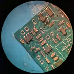
The MCU on the controllerboard has the markings 89F112 000, which appears to be the CMS89F112 from Cmsemicon.
It’s listed on jlc, for an estimated unit price of 0.3 USD. Hard to beat.
The datasheet is in chineese, but looks to have
A 2K x 14 bit flash memory (I’m unfamiliar with the practicality of 14 bit memory?).
144 bytes of RAM.
Inbuilt ADC, comparators, timers, PWM outputs, buzzer driver and a sleep mode.
A voltage range of 1.8-5.5V (at 4MHz, or from 2.5V at 8MHz).
A very capable little device. 144 bytes of RAM is not a lot, a bitfield for the LED matrix would take up 32 bytes, almost a quarter of memory. Still, that is absolutely enough for more complex or interesting effects on the matrix, like iterative or dynamic animations. My claim still stands: TE’s embedded developers dropped the ball on this one.
I found a couple of ikea frekvens LED matrix cubes from that teenage engineering collab in a thrift store in Vienna. They were cheap and I’d heard about people modding them.
Plugged in, they provide possibly the most dissapointing lightshow I’ve seen:
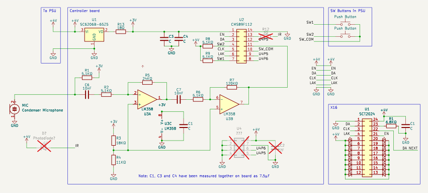
Whatever electronics they’ve got in there, it’s doing a very simple job: Show a static frame of a pre-baked five frame looping animation. Monitor a microphone and progress the animation each time a loud sound occurs. Check two buttons on the back to turn the LEDs on or off, and switch between a few different animation sets. That’s it. Nothing dynamic, nothing exciting. Why not make it just a bit more exciting?
Read More
A few existing projects:
funkyhome.de replace the inner controller board with an ESP-8266 to build modular desktop clocks.
SpritesMods install an ESP-CAM module by drilling through the LED matrix board to do tracking-based animations, building an IRL xeyes.
@frumperino on github began building a library for the cubes some years ago using the adafruit gfx library.
I think my general goals for modding are something like:
Maintain feature parity with the original cubes. As in, I don’t want to loose or add new aspects to the cubes. So no camera or wifi, but keep the microphone and buttons in use.
Be non-hacky and robust. I want to produce a result that can survive a drop or change in environment the same as the original cubes. So no levering solder joints or flying jumper cables, no need for setup.
Be economic. As in, be plausibly mass-producible in theory. Even if I’ll probably never come across any more of these things. (My suspicion is that they didn’t sell that well… I wonder why)
So basically, I think I’m trying to prove what kind of product the cubes could be if the TE software engineers had done a proper job…
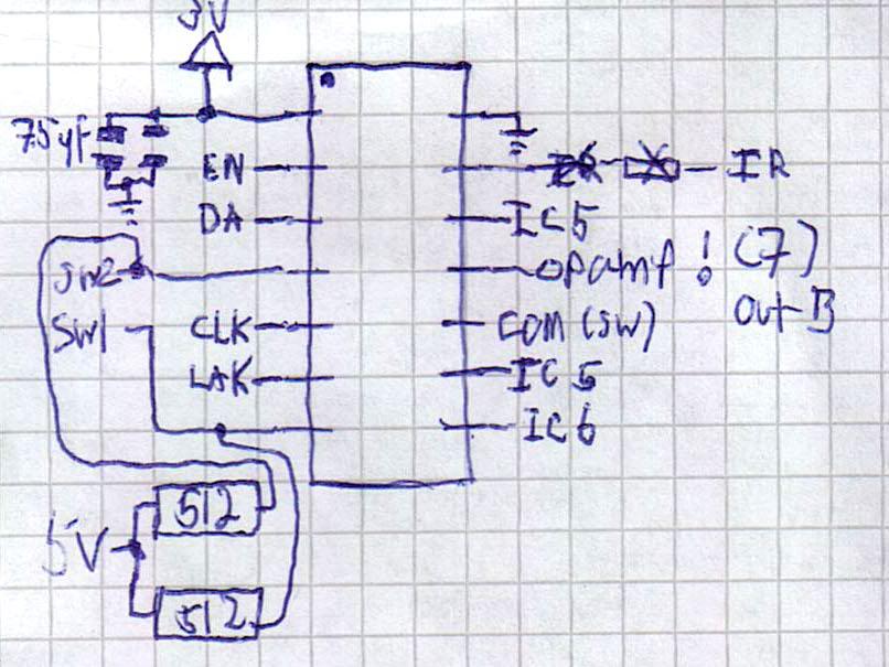
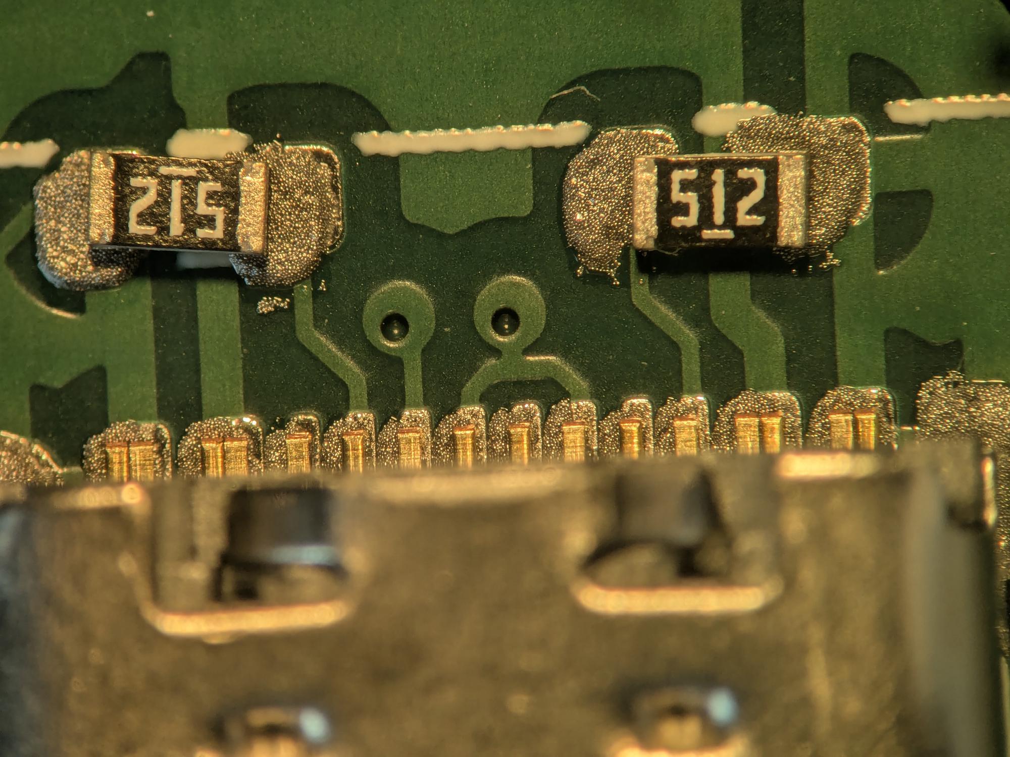
Soldering a v1.1 board of the flying checklist project. Blaming my tools in the solder paste being way out of date and unrefrigerated. Reflow went surprisingly well though. No tombstones, one bridge, a few unconnected pads.
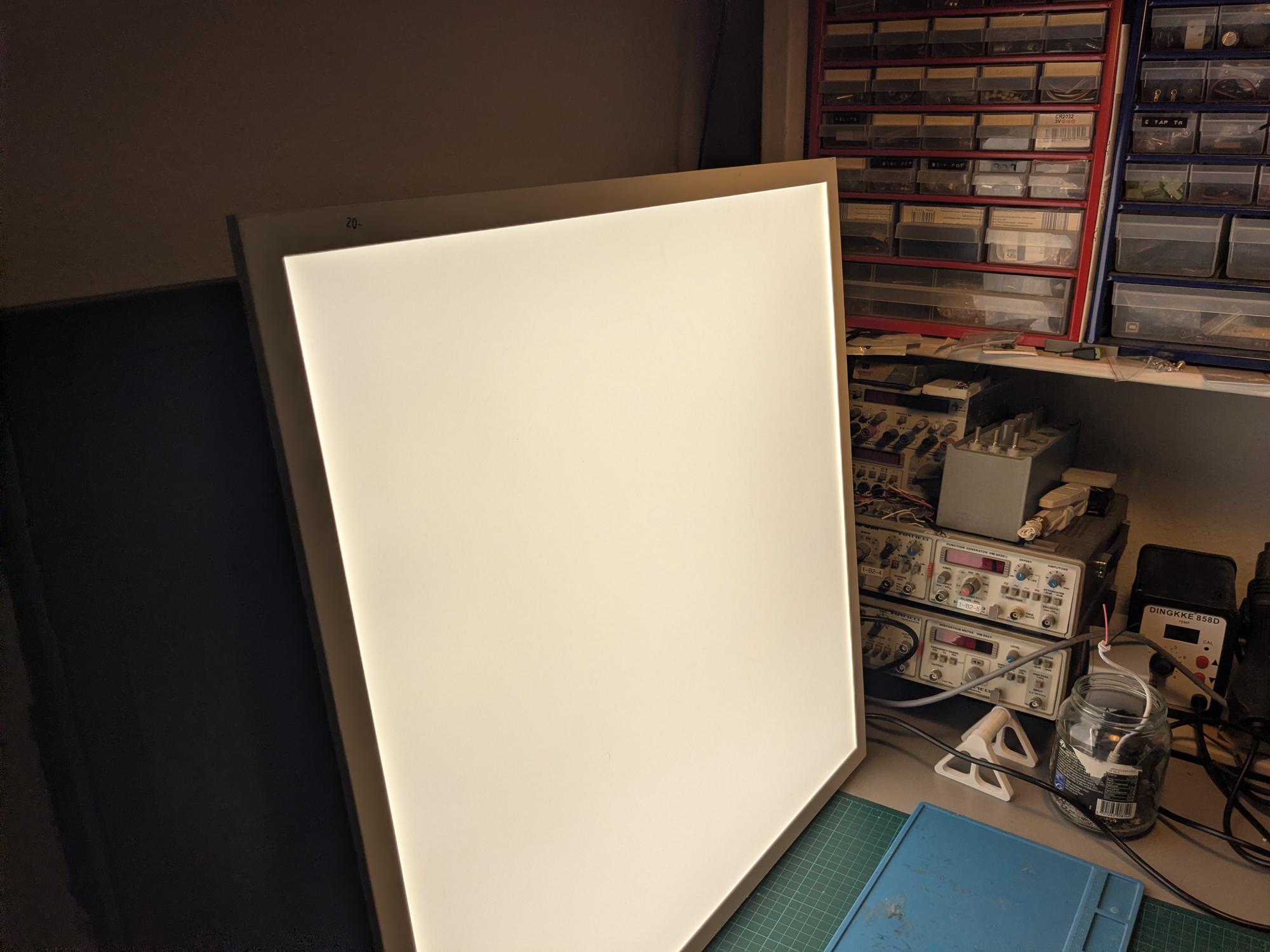
Found a 60x60 LED panel for 20dkk in the thrift store last week. Found an LED driver in the trash a couple days later. Just had to adjust the output power and change the power connector. Who knows, dali control might be broken, but I’m not living in an office. Think it’s gonna be my new work desk light.
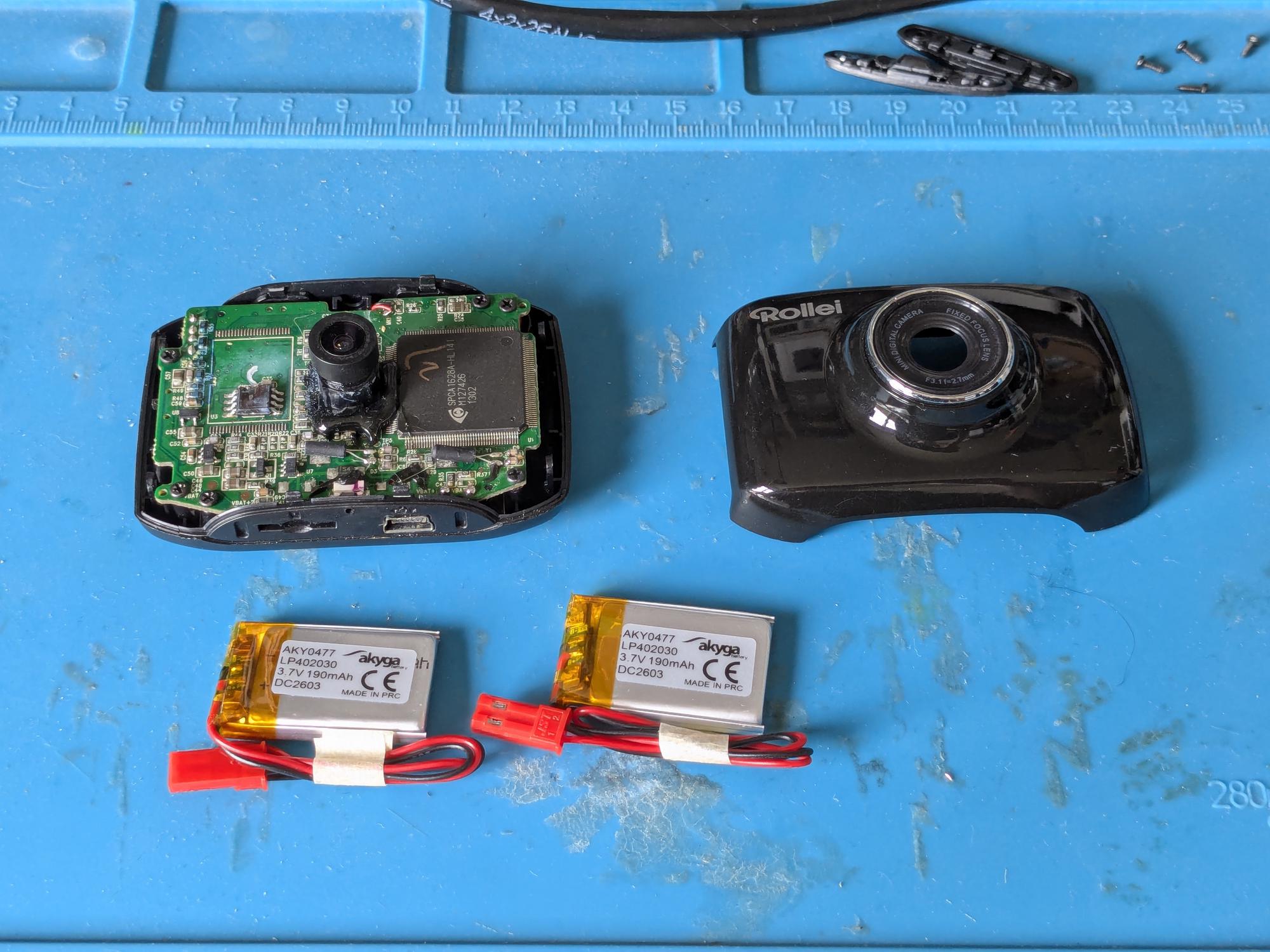
Bought a couple of the AKY0477 batteries from TME and got them installed. There’s a bit of free space around the camera lens where extra cable can be tucked in.
Batteries replaced aaand.. it works perfectly.
Now what in the world can I use a little action cam for…? I also found the cage for it with a broken hinge. Maybe worth fixing.
I found a Rollei action camera in the trash. Seems fully functional except it won’t take a charge.
The shell clicks open after removing the four visible screws at each side of the camera.
The camera has two lipo flat-packs wired in parallel and soldered to the board. Only one of the cells has a protection circuit, the other’s wired in behind it. Both cells have swollen significantly.